


When evaluating robotic machining, asking “what is the robot’s repeatability?” is the wrong opening question. The investment case depends on whether a named robot, base, spindle, tool, fixture, material, path, pose and control stack can repeatedly meet the part requirement under representative cutting force. This guide is for ASEAN plant managers, manufacturing-engineering leaders and capex approvers preparing an RFP or pilot for robotic cutting and robot milling. It turns a promising demonstration into a 90-day evidence programme with an explicit Go, Hold or No-Go decision.
Executive decision: robotic machining is not a universal machining-centre replacement
Robotic machining can be a strong candidate for large or complex low-volume parts, wide work envelopes, access from several directions, and flexible cells combining milling, drilling, deburring or grinding. A conventional machine tool may remain the better choice for stiffness-intensive heavy cuts, very tight tolerances, demanding surface finish or long thermal-stability windows. The decision should be based on whether the part’s critical-to-quality characteristics fit inside a measured process envelope—not on the equipment category.
At AMB Stuttgart on 15–19 September 2026, Siemens says it is demonstrating a high-precision CNC robot milling steel. On its CNC robotics page, Siemens calls its Machine Tool Robot the world’s most precise machining robot and claims more than 200% improvement in absolute path accuracy and up to 40% productivity improvement. These are Siemens vendor claims for its solution, not evidence that a generic six-axis arm will reproduce the result with another material, spindle, tool, fixture or pose. The timely demonstration shows why buyers should test a defined system rather than accept or reject the whole technology class.
The decision question is therefore:
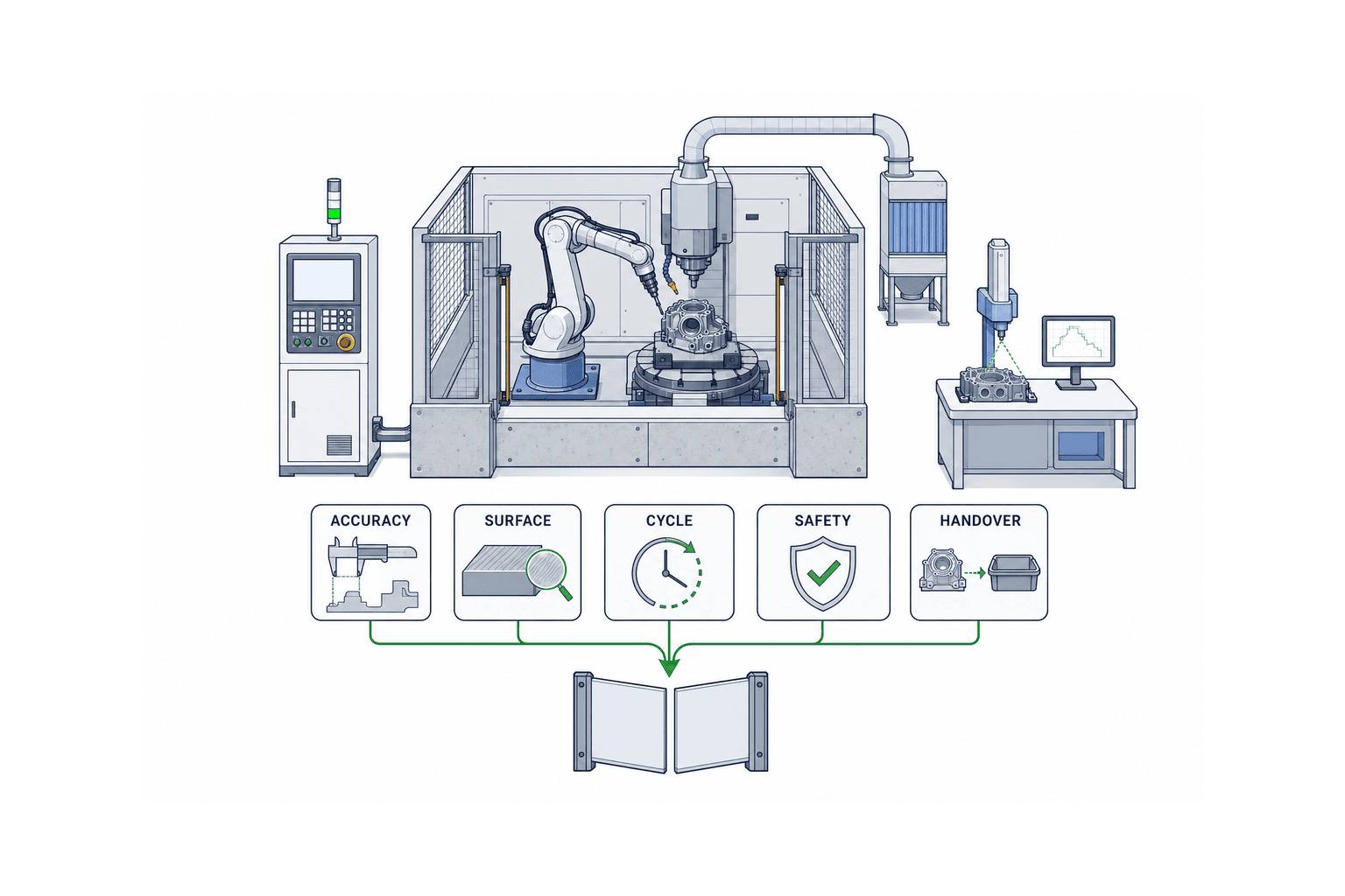
Has the proposed cell demonstrated, with reproducible data, a process window in which the representative part repeatedly meets dimensional, geometric, surface, cycle-time and safety requirements?
Define the complete robot milling system
An RFP that compares robot model numbers is incomplete. The delivered capability comes from the whole cell.
| System element | What the RFP must define | Evidence to retain |
|---|---|---|
| Robot and installation | Model, payload, reach, base, anchors, permitted poses | Layout and installation records |
| Spindle chain | Power/torque curve, speed range, cooling, holder, runout | Specification, runout and temperature logs |
| Cutting tool | Grade, diameter, stick-out, flutes, life policy, change method | Tool register, wear images and history |
| Workpiece/material | Grade, hardness range, stock variation, mass | Certificates, lot identity and measurements |
| Fixture | Datums, clamp sequence/force, support, deformation, re-clamping | Fixture drawing and repeatability test |
| Controls/software | CNC/robot control, CAD/CAM, postprocessor, compensation, versions | Version list, NC data and change log |
| Metrology | Probe, laser, CMM, roughness method and calibration | MSA, calibration and raw data |
| Peripherals/safety | Guarding, extraction, chips, coolant, fire and recovery | Risk assessment and validation tests |
Compare complete deliverable systems, not a robot-arm list price against a machining-centre list price. Include the base, spindle, cable package, control integration, fixtures, tools, extraction or coolant, guarding, metrology, programming, training and commissioning.
Four evidence layers: simulation approval is not cutting approval
Keep four evidence layers separate:
- Catalogue robot performance supports screening of reach, payload, repeatability and environment. It does not prove part capability.
- Offline simulation checks reach, collision, axis limits, poses, estimated cycle time, postprocessor and control logic. Tools such as Siemens Run MyVirtual Machine can test real control logic, NC data, postprocessors and virtual cycle time, but they do not prove physical deflection or chatter.
- No-load path measurement checks coordinate frames, calibration, directional effects and trajectory without representative cutting force.
- Loaded cutting on coupons or representative parts uses the agreed material, tool, stick-out, spindle, feed, speed, depth, fixture and pose. Only this layer demonstrates the usable process envelope.

One attractive sample is only an entry into the fourth layer. A single part cut in the most favourable posture says little about the full workspace, tool wear, thermal drift, restart, re-clamping or material-lot variation. Raw conditions and raw measurements must be contract deliverables.
Robotic machining accuracy needs more than one number
Monodirectional and multidirectional repeatability
Returning to a point from the same approach direction differs from reaching it through different paths and directions. The Siemens Run MyRobot commissioning manual explains that multidirectional repeat accuracy is relevant for CAD/CAM-generated or dynamically offset paths and is worse than monodirectional repeat accuracy. That is why one catalogue repeatability figure cannot accept a complex tool path.
Absolute and path accuracy
Absolute accuracy describes proximity to the commanded coordinate; path accuracy concerns the motion between points. Calibration and model compensation may improve both, but installation, temperature, payload, pose and tool-centre-point definition affect the result.
Load deflection
Machining creates force between tool and workpiece. An open-access review of industrial robots in machining identifies insufficient TCP rigidity as a major limitation and notes that vibration can degrade surface quality and accuracy and contribute to tool breakage. A separate stiffness review cites a literature example in which a 500 N cutting force produced roughly 1 mm error in a serial robot versus under 0.01 mm in a CNC machine tool. This is an illustrative literature case, not a universal design value. Measure the proposed cell.
Thermal drift, vibration and surface finish
Spindle warm-up, motors, ambient conditions and long runs can shift position and geometry. Chatter may show up in roughness, tool life, sound and spindle load even when an isolated dimension passes. Acceptance must cover the end of tool life and a sustained operating period, not just a fresh tool.
ISO 9283:1998 provides industrial-robot performance criteria and test-method vocabulary. It was confirmed in 2021 and is under revision in 2026. It is a useful reference for defining robot tests; an ISO 9283 result is not proof of part capability for a specific material, tool and fixture.
Build a pose-and-direction capability map
The stiffness and error of a serial robot change with posture. Test the actual operating workspace, not one “representative” point. A 3×3 grid is an illustrative project design that can communicate nine test positions clearly; it is not an ISO requirement. The part size, access faces, installation and weak postures should determine the final points.
| Data field | Record at every point |
|---|---|
| Configuration | Cell, robot, spindle, tool, fixture, material lot and software version |
| Pose | Joint angles, TCP position, tool direction, approach direction and base distance |
| Cutting recipe | Speed, feed, axial/radial depth, tool stick-out and path |
| Force proxy | Agreed spindle load, motor current, force sensor or vibration value |
| Geometry | Individual deviations, distribution and measurement uncertainty |
| Surface/tool | Roughness, chatter marks, burrs, wear, damage and life position |
| Time/state | Cycle, stops, retries, temperature, warm-up and alarms |
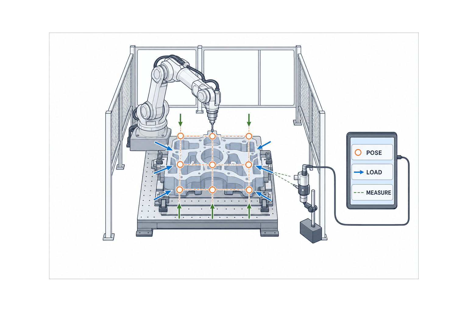
Do not reduce the map to a red/amber/green picture with no traceable data. A green area is valid only inside the agreed material, tool, stick-out, cutting recipe, pose and temperature window. The map becomes the baseline for later change control.
The RFP data contract
Sending only a 3D model will not produce comparable proposals. Add a controlled data schedule.
Part drawings and CTQs
- 2D drawing, 3D model, datum structure, geometric tolerances, roughness and edge condition
- Material specification, hardness range, stock condition and upstream casting, welding or additive process
- Stock allowance, finishing allowance, machined faces, access limits and part mass
- Measurement method, points, sampling plan and decision owner for each CTQ
Spindle, tool and fixture
- Spindle power/torque curve, speed range, cooling, runout and interface
- Tool grade, geometry, diameter, flutes, stick-out, holder, life and regrind rules
- Fixture datums, clamp sequence and force, support, deformation, re-clamping and maintenance
Path, coordinates and software
- Versions of CAD/CAM, postprocessor, robot/CNC control and compensation functions
- Definition and calibration of TCP, base and work coordinates; recalibration triggers
- Poses, approach directions, singularity/axis-limit avoidance, interpolation and speed limits
- Ownership and handover format for programs, parameters, raw logs, measurement data and models
Safety, operation and recovery
- Guarding, doors, interlocks, safe speed/space, emergency stops and restart logic
- Controls for chips, dust, coolant, mist, noise, fire, tool breakage and ejection
- Safe recovery after power loss, spindle stop, tool break, work shift or communications loss
- Consumables, preventive maintenance, calibration, backup, version updates and local support
Require suppliers to mark each response as standard, configuration, custom development, third-party or excluded, then state assumptions, limitations, cost, lead time, maintenance responsibility and test evidence. “Supported” alone is not a scorable answer.
A 90-day robotic machining pilot
Ninety days is a governance example, not a universal technical requirement. Adapt it to procurement lead time, part difficulty and shutdown constraints.
Weeks 1–2: requirements and baseline
Freeze representative parts, CTQs, volume and mix, current cycle, outsourced lead time, scrap/rework, tooling, labour and stoppage reasons. Measure current machine-tool or outsourced output with the same metrology planned for the pilot. Review measurement-system capability and uncertainty so metrology noise is not mistaken for cell variation.
Weeks 3–4: cell and process design
Design robot pose, installation, spindle, tools, fixture, extraction/coolant, metrology and safety together. Review weak postures, cable twist, chip flow, tool changes, cleaning and maintenance access—not only reach. Use FMEA for dimensional drift, chatter, tool failure, workpiece ejection, dust, coolant leakage and recovery errors.
Weeks 5–6: simulation and calibration
Virtually test collision, limits, singularity, path, estimated cycle, postprocessor and logic. On the physical cell, calibrate base, TCP and work coordinates and measure the no-load path. Record the difference between virtual and physical no-load cycles, but do not declare machining capability yet.
Weeks 7–9: coupon and workspace tests
Begin with safe, low-load cuts on representative material. Within an agreed experimental range, vary speed, feed, depth, tool stick-out and pose. Repeat at capability-map points and record geometry, surface, load, vibration, temperature, tool wear and time. Predefine warning and stop criteria as well as success criteria.
Weeks 10–11: representative parts and recovery
Run parts across material lots, tool-life positions, cold/warm states, re-clamping and restart. Inject agreed failures such as an alarm, tool replacement, spindle stop or work-detection fault, then verify safe recovery to the same quality distribution. Evaluate the agreed sample plan, not one favourable part.
Week 12: evidence package and decision gate
Deliver the configuration record, drawings, risk assessment, programs, parameters, versions, calibration, raw logs, measurements, capability map, tool-life evidence, incidents, recovery results, open issues, TCO assumptions, training and maintenance package. Go means production deployment, Hold means a limited additional test against named gaps, and No-Go means the application is not accepted. A clear No-Go still creates useful knowledge by defining the boundary.
Acceptance matrix: agree the variables and thresholds before testing
The table is a template. There is no universal numeric threshold; buyer and supplier must set values for the named part and process.
| Acceptance area | Variables/questions | Required evidence | Decision form |
|---|---|---|---|
| Geometry | CTQs, pose variation, distribution, uncertainty | Raw CMM data and capability map | Pass / limited window / fail |
| Surface | Roughness, chatter, marks and burrs | Values, photographs and agreed visual sample | Drawing/sample conformity |
| Throughput | Cut, tool change, measurement, cleaning, recovery | Time logs and sustained run | Meets agreed demand window |
| Tool life | Wear, breakage, interval and variation | Tool register and life curve | Predictable and economic |
| Stability | Stops, retries, scrap and manual intervention | Continuous test and alarm history | Stable for agreed duration |
| Recovery | Power, breakage, shift and communication faults | Fault injection and recovery record | Safe return to controlled quality |
| Containment | Chips, dust, mist and coolant | Leakage, build-up and cleaning evidence | Risk controls effective |
| Safety | Guarding, stop, door and restart | Validation and test records | Agreed standards/local rules met |
| Traceability | Material, tool, version, work and measurement links | Identifier-to-log reconciliation | All conditions traceable per part |
| Reproducibility | Re-clamp, restart, recalibration and shifts | Re-run distribution | Same agreed window |
| Handover | Drawings, code, backup, training and spares | Document list, restore and skill test | Plant can maintain and reproduce |
Safety: robot-cell hazards and machining hazards are not the same list
ISO 10218-2:2025 covers integration and safety of industrial robot applications and cells. The ISO summary also indicates that hazards arising from material processing itself are outside its covered hazard list. Citing the robot standard alone therefore does not complete the machining-cell risk assessment.
In addition to robot motion, speed, space, guarding and interlocks, assess high-speed spindle and rotating-tool hazards, tool breakage, workpiece/chip ejection, dust and mist, combustible material, coolant, noise, heat, sharp swarf, cleaning, maintenance, jam clearing and restart. Include teaching, setup, measurement, tool change and abnormal recovery. Confirm Thai legal, site, insurer and customer requirements with qualified project stakeholders.
Economics: compare delivered systems and usable operating windows
Compare the total cost of a complete cell against a complete alternative:
Robot option TCO = arm/control + base + spindle/tool change + fixtures + guarding/extraction/coolant + metrology + integration/programming + training + maintenance + tools/consumables + energy + labour/monitoring + scrap/rework + downtime − residual/reuse value.
Alternative TCO = machine tool or outsourcing + fixtures/tools + installation/building + programming + logistics/WIP + quality cost + lead-time impact + maintenance + people − residual value.
Use measured good-part cycle time including tool changes, inspection, cleaning, setup, faults and product changeover. Benefits may include avoided transport of large parts, shorter queues, faster design changes, process consolidation and reuse of the cell, but each must have a named baseline and owner.
Hypothetical, recalculable example—not a market quote or performance promise
Assume a delivered robot cell costs THB 12.0 million and the alternative THB 16.0 million. Assume the robot option adds THB 1.0 million per year in programming, maintenance, tooling and quality cost, while avoiding THB 2.6 million per year in outsourcing, logistics and waiting losses. Net annual benefit is THB 1.6 million; the THB 4.0 million initial difference gives a simple payback of 2.5 years: 4.0 ÷ (2.6 − 1.0) = 2.5.
Every number is hypothetical. It is not a price, utilisation forecast, tax opinion or BOI result. Run sensitivities for good-part cycle, utilisation, tool cost, scrap, outsource rate and demand. If the cell falls outside its proven process window, rework can reverse the conclusion.
A Thailand BOI/OSOS July 2026 release says 132 first-half 2026 applications worth about THB 17.2 billion were submitted under Smart and Sustainable Industry for machinery upgrades, digital technology, automation and robotics. This is investment context, not a guarantee that a project receives incentives. Confirm activity, eligible cost, timing and conditions for the specific Thai project. Thai BOI rules must not be presented as applying to plants in Vietnam or another country.
Procurement checklist before buying a CNC robot
- [ ] Named parts, materials, CTQs, surfaces, volume, mix and upstream/downstream processes are fixed.
- [ ] The reason for robotics—workspace, flexible access or process combination—is explicit.
- [ ] Machine-tool, outsourcing and process-redesign alternatives are compared.
- [ ] The complete cell, not only the arm, is under configuration control.
- [ ] Catalogue, simulation, no-load and loaded-cut evidence are separated.
- [ ] Pose, approach direction and cutting load are included in a capability map.
- [ ] Raw logs, NC, post, compensation, calibration and measurement ownership are contracted.
- [ ] Tool wear, cleaning, chips/dust, coolant and recalibration are standard work.
- [ ] Failure recovery, restart and re-clamping are tested.
- [ ] Process-specific hazards are assessed in addition to robot safety.
- [ ] Local-language training, shift support, spares, backup and version control are included.
- [ ] The plant team can safely stop, restore and verify the process without the integrator present.
For the virtual layer, see our robot simulation and virtual commissioning guide. To separate cutting from downstream finishing, see deburring automation 2026. Existing control-asset decisions can be structured with the PLC replacement and retrofit decision guide.
FAQ on robot milling deployment
Can robotic machining achieve machining-centre accuracy?
There is no universal answer. Robot structure, compensation, spindle, tool, fixture, material, force, pose and temperature matter. A particular system may meet a named requirement, but that does not transfer automatically to another cell. Use loaded representative cutting and a pose-based capability map.
Is catalogue repeatability sufficient if it is inside the drawing tolerance?
No. Check how it was measured, directionality, absolute/path error, TCP definition, load deflection, vibration and thermal effects. Catalogue data screens candidates; the cutting trial accepts the process.
How many parts should the 90-day pilot cut?
There is no universal count. Quality, engineering and statistical owners should set the sample plan from the number of CTQs, expected variation, material lots, tool life, poses, metrology capability and required confidence. The purpose is a decision-ready distribution, not a single success.
Is the 3×3 capability map required by ISO?
No. It is an illustrative way to expose workspace and posture differences. Set the actual grid, approach directions and repetitions from the cell and workpiece.
Can simulation reduce physical testing?
It can reduce risks in reach, collision, limits, control logic, NC and postprocessing. It cannot prove cutting-force deflection, chatter, wear, heat or chip behaviour. Simulation makes physical testing safer and more focused; it does not replace it.
Does a robotic machining investment in Thailand automatically receive BOI incentives?
No. Published statistics show application activity, not project entitlement. Confirm eligible activity, cost, timing and conditions before committing equipment.
Summary: buy a reproducible process window, not one good sample
A robotic machining investment should deliver a defined process envelope in which the complete cell repeatedly meets geometry, surface, cycle-time and safety requirements. Separate catalogue performance, virtual validation, no-load measurement and loaded cutting. Put the capability map, recovery tests, raw data and handover package into the RFP so the capex gate can reach an explainable Go, Hold or No-Go outcome.
If you are still deciding whether robot milling fits your parts, TOMAS TECH can help structure the CTQs, alternatives, RFP and 90-day evidence plan before a supplier is selected. Contact TOMAS TECH to discuss the evaluation scope.
Sources
- Siemens at AMB Stuttgart 2026 — vendor event announcement, 15–19 September 2026
- Siemens CNC Robotics — Siemens product claims on accuracy and productivity
- Siemens Run MyRobot commissioning manual
- KUKA milling application — KUKA states approximately ±0.4 mm for CRP/GRP; do not generalise it to steel or another cell
- ISO 9283:1998
- ISO 10218-2:2025
- Industrial Robots in Machining: A Review
- Stiffness Modeling of Industrial Robots: A Review
- Thailand BOI/OSOS first-half 2026 investment release
- Siemens Run MyVirtual Machine


