


The real decision in a robot simulation implementation is not whether to buy the most advanced simulator. It is which risks must become observable before factory acceptance, and which residual risks must remain for physical FAT/SAT. This guide gives ASEAN production-engineering and plant managers a practical way to specify virtual commissioning in an RFP and accept—or reject—a 90-day pilot. It covers model inputs, SiL/HiL, collision and cycle-time tests, vision variation, evidence and reusable handover assets.
Executive decision: when robot simulation belongs in the RFP
Simulation is valuable when discovering a problem on the physical cell would materially affect delivery, safety, quality or production downtime. Typical candidates include tightly coordinated robots, dense PLC interlocks, a very short shutdown window for an existing line, vision-led process capability, or an engineering team located far from the destination plant.
A low-fidelity reach and interference study may be enough for a simple pick-and-place cell based on a proven standard design with ample debugging time. HiL is not automatically better: modelling, calibration and maintenance also consume budget. Select the verification level from the risk to be controlled.
Start with five questions:
- Which failures would be expensive if first discovered on the real cell?
- Can geometry, controls, sensor or timing models expose them credibly?
- What uncertainty remains even after a simulation pass?
- Who can rerun the evidence, and to which model and code versions is it tied?
- Can the plant reuse the model for a new product, retrofit or sister line?
Without these answers, “digital twin included” may result in little more than a video, screenshots and a proprietary model that the plant cannot reproduce.
Four verification levels: offline programming is not virtual commissioning
The term robot simulation covers activities with very different evidential value. Siemens describes robotics virtual commissioning as testing actual control software against a digital twin before deployment. Offline robot programming alone therefore does not prove PLC logic, real I/O or controller timing.
| Level | Main components | What it can establish early | What it cannot establish alone | Typical RFP deliverable |
|---|---|---|---|---|
| Geometry and reach | CAD, robot envelope, simplified tool | Reach, layout and gross interference | Actual controls, dynamics or production cycle | Layout, clash list, unreachable points |
| Offline programming | Robot type, TCP, path and posture | Programme draft, posture and path collision | PLC sequence, real I/O and network delay | Robot programme and conversion assumptions |
| SiL | Virtual controller, PLC/HMI code and I/O model | Logic, state transitions, recovery and repeatable scenarios | Hardware-specific timing, wiring and shop-floor friction | Executable model, cases and logs |
| HiL/control-faithful VC | Real/equivalent controller, network and digital twin | Control cycle, I/O, communications and production code interaction | Every installation, wear, lighting and grasp variation | Configuration, rerun method, gap and residual-risk register |
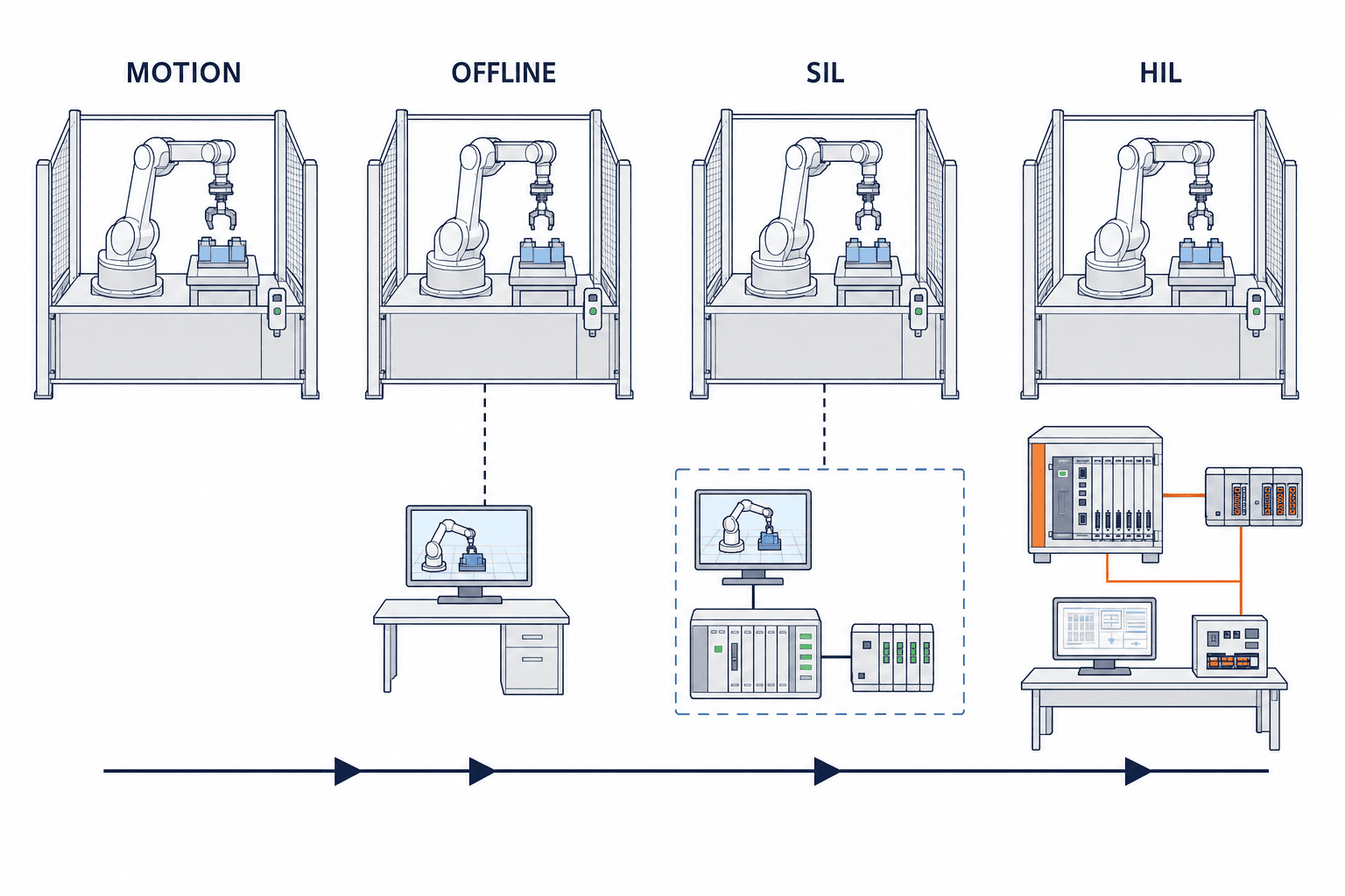
Use the lowest level that can answer the decision. Geometry may support a capital layout review. SiL is appropriate when recovery logic is the schedule risk. HiL is warranted when the real controller and industrial-network timing matter.
Six sources of the sim-to-real gap
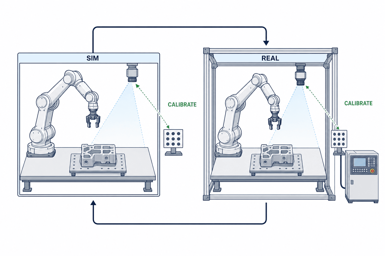
A robot digital twin is not a perfect copy of reality. It is a model of the parts of reality required for a defined purpose. ISO 23247-1:2021 provides an overview and general principles for a manufacturing digital-twin framework; it does not certify a simulator or guarantee accuracy. An RFP should name inputs, assumptions, calibration and tolerances instead of relying on the label “digital twin”.
1. Geometry and coordinate frames
Even a current CAD assembly may omit a modified fixture, cable, bolt head, cover or sensor bracket. Define how robot base, work, TCP, camera and fixture frames are measured and who updates them. Reconcile safety-critical clearances with physical measurements, not drawings alone.
2. Dynamics, payload and grasp
Mass, centre of gravity, inertia, acceleration, compliant parts, vacuum response and gripper deflection affect both posture and cycle time. A simulated time is not automatically a measured production time. Record the error by cycle segment.
3. Controller and firmware equivalence
The same robot arm can behave differently with another controller generation, firmware, option package, interpolation mode, speed limit or safety configuration. Require a mapping between the virtual controller and the physical target.
4. PLC, I/O and network timing
Response delays, bouncing signals, timeouts, retries, power recovery and manual resets are common gaps. For SiL/HiL, freeze PLC scan, communication update, time synchronisation and signal initialisation, and capture them in the result log.
5. Sensors, lighting and materials
Vision inputs change with illumination, reflection, colour, position, background, lens contamination and material batches. NVIDIA presents Isaac Sim as an open-source reference framework for physics-based simulation, synthetic-data generation and SiL/HiL testing. Its documentation describes converting CAD, URDF and real-world inputs to USD and varying lighting, reflection, colour and position. This is useful for stress testing, but a synthetic-data pass does not guarantee performance on real images. Hold out physical samples that were never used for tuning and test them during SAT.
6. Wear and plant variation
Backlash, floor vibration, dust, tool wear, feeding error and operator intervention cannot all be modelled perfectly. Put these items in a residual-risk register and link them to a physical SAT case instead of declaring them “simulated”.
The RFP model and data contract
Do not procure “one simulation package”. Procure the inputs required to rebuild and rerun it. For every input, specify provider, version, unit, coordinate system, receipt date, approver and the permitted assumption if it is missing.
| Data group | Minimum inputs | Acceptance check | Owner/update responsibility |
|---|---|---|---|
| Geometry | CAD revision, fixtures, equipment, fence, cable volume | Critical dimensions, physical difference, omitted parts | Mechanical design and plant engineering |
| Robot | Model, controller, firmware and options | Match to nameplate and backup | Robot integrator |
| Tool | TCP, mass, centre of gravity, inertia, actuation time | Calibration and payload settings | Tool supplier and integrator |
| Workpiece | Tolerances, material, surface and pose range | Nominal and boundary samples | Quality and production engineering |
| Controls | PLC/HMI revision, I/O list, tags and state model | Source-control commit | Controls engineer |
| Sensor | Type, field of view, resolution, latency, lighting range | Installed configuration, calibration and hold-out set | Vision/sensor owner |
| Time | Cycle start/end, exclusions and stoppage rules | PLC/MES/video clock reconciliation | Industrial engineering and controls |
| Test | Scenario ID, initial state, input and expected output | Automated rerun and evidence export | Plant acceptance owner |
Define cycle time precisely. Is it from first workpiece detection until the next piece can enter, or only active equipment time? Does it include robot waiting, upstream starvation, regular cleaning or tool change? Report by product, mode and bottleneck segment, not only as one average.
Link CAD, robot programme, PLC, HMI, vision settings, scenarios and logs to a common release ID. A change after a pass must trigger the affected regression cases. The handover requires this traceable manifest, not just the final files.
Acceptance matrix: separate simulation pass from FAT/SAT pass
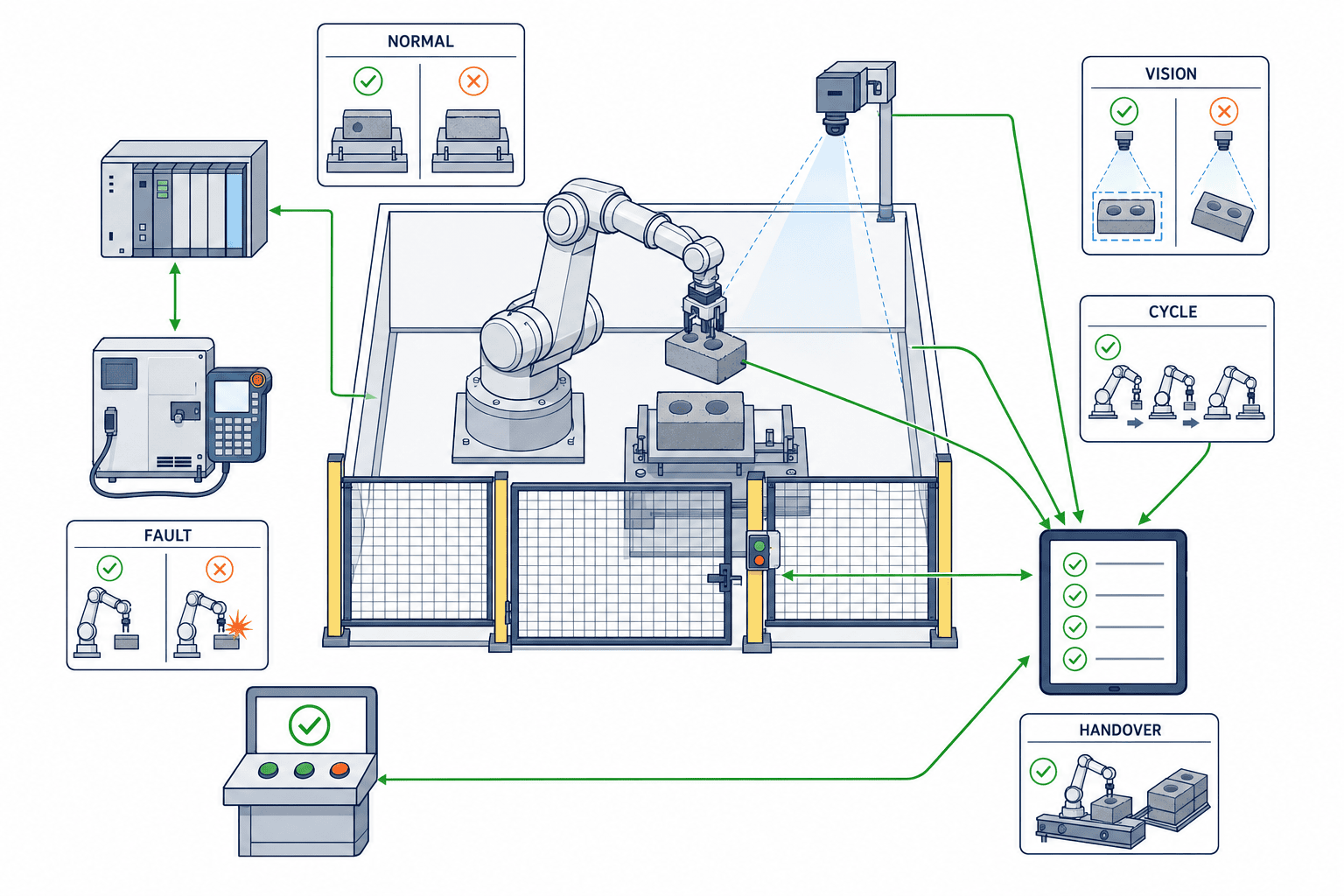
Each risk needs a virtual criterion, a physical confirmation, tolerance, evidence and owner.
| Test family | Example virtual pass | Confirmation retained for FAT/SAT | Mandatory evidence |
|---|---|---|---|
| Normal operation | Expected transitions for every product | Continuous run with real I/O and parts | Scenario log, version ID and video |
| Boundaries | No unhandled result across dimension, pose and payload range | Physical limit parts and fixture measurement | Inputs, outputs and exclusion reason |
| Fault recovery | Safe recovery from missing sensor, failed grasp and stop | Wiring break, reset and power restart | Operator steps, alarm and recovery time |
| Collision/clearance | Defined minimum clearance met | Cable, deflection and installation measurement | Closest pair, distance and posture |
| Throughput/cycle | Segment time within virtual tolerance | Distribution measured on real controller | Segment log, waiting cause and delta |
| Vision | Criteria met on varied and held-out synthetic scenes | Untuned physical images and edge pieces | Dataset version, confusion matrix and failures |
| Traceability | Case links to requirement, code and model | Backup matches commissioned cell | Trace matrix and checksums |
| Handover | Another workstation can rerun the suite | Plant engineer follows the procedure | Runbook, licences and training record |
Project-specific numbers, not invented standards
Let C_req be required clearance, C_min simulated minimum clearance, T_sim simulated cycle, T_real the SAT median and δ an agreed tolerance. Criteria may be expressed as C_min ≥ C_req and |T_real − T_sim| / T_real ≤ δ. This article does not prescribe C_req or δ. They must follow the robot, tool, cable, hazard assessment, process capability and measurement resolution.
Do not accept only an average cycle. Retain outliers and their causes. For vision, replace one “accuracy” number with class-level recall, false detection, reject rate and processing latency. Safety functions must follow the applicable risk assessment, standards and formal physical validation; simulation is not approval.
Turn every test result into a reproducible evidence package
To avoid “it worked last week” at the acceptance meeting, store every scenario in the same evidence unit. At minimum record the requirement ID, scenario ID, execution time and operator, model release, robot/PLC/HMI/vision versions, initial state, inputs, expected result, measured result, judgement, log reference and known limitations. Video helps people understand the event, but it cannot by itself prove signal order or software version; pair it with machine-readable logs.
Classify a failed test rather than writing only “adjust and retest”. A model defect means that CAD, physical properties, timing or sensor conditions do not represent reality well enough. An implementation defect means that robot, PLC, HMI or vision code does not meet the requirement. A test defect concerns initial conditions, ground truth, instruments, synchronisation or procedure. Residual variation exists in reality but lies outside the agreed model and must move to SAT. Without this classification, a model problem can be hidden by site tuning or a software defect dismissed as simulation error.
Retest the changed case and the already-passed cases that may be affected. A TCP change, for example, can affect reach, closest clearance, cable posture, cycle segments and the camera field of view. A trace matrix linking requirements, model elements and tests explains the regression scope. The whole suite need not run after every change, but every excluded case needs a recorded reason.
The plant acceptance owner should read a sample evidence package before the final week. A quality engineer without the specialist simulator should still be able to identify what was required, which version ran, what was entered and why it passed. If the execution environment remains in the supplier cloud, contract post-termination viewing, export, rerun rights and retention. Model ownership alone has little value when required licences, plug-ins or conversion tools are absent.
If defect count is used as a benefit measure, record severity and discovery stage. Do not inflate the result with many minor display discrepancies. Record the likely impact if found on the physical cell, the correction effort, and any requirement or standard-component change that prevents recurrence. This separates the benefit of virtual commissioning from a general improvement in engineering quality.
Separate the checks that cannot close virtually
At RFP stage, split the acceptance scope into checks closed in simulation, checks retained for FAT and checks possible only after installation in SAT. Paths, PLC sequences and fault-recovery logic can move forward. Actual cable behaviour, fixture deflection, worn-part variation, floor vibration, ambient light, operator intervention and plant-network congestion still need physical conditions. A retained check is not a failure if it is deliberately transferred to the physical plan. For every retained check, record why it is outside the model, the expected impact, interim control, physical test case, owner, equipment state, measurement method, due date, acceptance rule and route back when it fails. Writing only “out of simulation scope” blurs the boundary and lets the supplier and plant each assume the other owns the check.
Also contract how physical-cell changes return to the model. If installation changes a sensor position, cable route, fixture dimension or PLC timer without updating the model, reuse value falls quickly. The final baseline should reconcile the model with the commissioned cell, while every unresolved difference remains in a known-limitations register.
A 90-day pilot plan
The pilot is not simply a model-building period. It measures the model-to-plant gap and turns the result into evidence suitable for a production RFP.
| Period | Purpose | Main work | Gate deliverable |
|---|---|---|---|
| Weeks 1–2 | Scope and baseline | Cell, failure modes, current debug effort, cycle definition, data ownership | Approved requirements and matrix |
| Weeks 3–4 | Build | CAD, frames, TCP, control versions, I/O, sensor conditions and assumptions | Executable model v1 |
| Weeks 5–7 | Virtual test | Normal, boundary, fault, recovery, collision, cycle and vision cases | Results and defect tickets |
| Weeks 8–9 | Physical reconciliation | Measure dimensions, segment times, I/O, images and calibration target | Sim-to-real delta table |
| Weeks 10–11 | Gap correction | Classify model, implementation, measurement and residual-variation causes; retest | Release candidate and open list |
| Week 12 | Decision preparation and handover | Independent rerun, value review, production scope and training | Draft decision and handover candidate |
| Days 85–90 | Final gate and contingency | Recheck open deltas, approval, contingency retest and ownership transfer | Go/Conditional/No-Go package |
Freeze criteria by Week 2 and control later changes. Do not finish at the first virtual pass. Physical reconciliation is the point at which the team learns whether the model supports a plant decision. Twelve weeks are 84 days; reserve the remaining six days for open-delta retest, final approval and ownership transfer.
Go/Conditional/No-Go decision rules
- Go: critical requirements pass, residual risks have SAT cases and owners, and another engineer can rerun the work.
- Conditional: a bounded data or model gap remains with an agreed due date, cost, responsible owner and retest.
- No-Go: critical cases cannot be reproduced, results are not versioned, physical discrepancies remain unexplained, or reuse rights are unavailable.
A polished screen and a moving robot are not acceptance criteria. Report both the defects found early and the important defects the virtual test missed.
Cost model without fabricated market prices
Use variables because licences, robot count, engineering rates and safety scope differ greatly:
C_total = C_model + C_licence + C_compute + C_integration + C_testdata + C_calibration + C_training + C_maintenance
V_avoided = H_debug × R_team + H_stop × R_stop + C_prototype + C_rework + V_reuse
Net value = V_avoided − C_total
H_debug is avoided on-site debugging time and R_team is the fully loaded hourly rate of the participating team. H_stop is avoided production stoppage and R_stop is the opportunity cost per stopped hour. C_prototype is avoided prototype cost, C_rework is avoided physical modification cost, and V_reuse is the value of actual reuse on another product or line. Measure saved time as the difference between an agreed baseline and project records, not as a sales estimate, and count reuse only when the model is demonstrably usable.
Vendor-claim box: useful context, not the ROI input
ABB and NVIDIA state that RobotStudio HyperReality combines RobotStudio with physically accurate Omniverse simulation to narrow the sim-to-real gap. ABB stated general availability in the second half of 2026 after selected-customer trials. In a March 2026 release ABB also claimed up to 99% accuracy, up to 80% shorter setup/commissioning, up to 40% lower cost, 50% faster time-to-market, and Absolute Accuracy improving nominal positioning error from 8–15 mm to around 0.5 mm. These are vendor-specific statements, not independent benchmarks, and must not be generalised to every robot, camera, process or plant.
Siemens states on a service page that virtual commissioning can shorten real commissioning by up to 70%. This is also a supplier claim, not a universal result. Keep such claims as context and replace them with pilot measurements before approving a business case.
Make or buy—and questions for the systems integrator
An internal capability fits plants that change products frequently, reuse models and own their mechanical and control sources. An integrator can accelerate access to specialist robot, simulator and HiL expertise. A practical hybrid is to outsource model build while the plant retains requirements, acceptance, physical measurements and release approval.
For teaching effort and outsourcing boundaries, see Robot Teaching and Programming. A welding cell should also incorporate the process variation described in AI Welding Agent and Robot Implementation. For human interaction and operational design, use the Collaborative Robot Implementation Guide and never treat simulation as a substitute for physical safety validation.
Ask every bidder:
- Which requirement is verified by geometry, offline programming, SiL or HiL?
- Which physical controller and firmware does the virtual controller represent?
- How are missing CAD and assumptions registered?
- Who measures and approves TCP, payload, inertia and frames?
- How is the tested PLC/HMI/I/O version proven?
- How are cycle start, end and downtime defined?
- Can fault, communication-loss and restart cases run repeatedly?
- How are vision variation and held-out real samples handled?
- Which cases remain for SAT after a virtual pass?
- What model, script, log, licence and training assets are handed over?
- Can the plant rerun them on another workstation?
- Who owns changes, regression scope, maintenance cost and data rights?
Procurement and acceptance checklist
- [ ] Risks and explicit non-claims of simulation are written.
- [ ] Each requirement has one of the four verification levels.
- [ ] CAD, controls, TCP, payload, I/O and sensor versions have owners.
- [ ] Normal, boundary, fault and recovery scenarios have unique IDs.
- [ ] Clearance and cycle definitions, tolerances and measurements are agreed.
- [ ] Vision testing includes variation and untuned physical samples.
- [ ] Simulation, FAT and SAT criteria are separate.
- [ ] Results trace to requirement, code, model and log versions.
- [ ] Sim-to-real gaps and residual risks are visible.
- [ ] The plant receives rerunnable assets and usable licence terms.
- [ ] Benefits are measured from the plant baseline, not supplier headlines.
- [ ] A named owner makes the 90-day Go/Conditional/No-Go decision.
FAQ
Can robot simulation implementation eliminate physical FAT/SAT?
No. Installation error, cable motion, wear, real communications, lighting, materials and safety functions still require physical checks. Virtual commissioning focuses FAT/SAT on the highest residual risks.
What is the difference between offline programming and virtual commissioning?
Offline programming mainly prepares path, posture and robot code away from the cell. Virtual commissioning connects production PLC/HMI or controller-faithful software to the digital twin to test state, I/O, recovery and timing.
What percentage accuracy should a robot digital twin achieve?
There is no useful single percentage. Define error and tolerance for each decision: dimensions, TCP, closest clearance, cycle segment and vision outcome. Keep vendor figures separate from plant acceptance.
How should vision be accepted across sim-to-real?
Vary lighting, reflection, colour and pose in simulation, then evaluate physical images and parts withheld from tuning. Report class recall, false detections, rejects and latency rather than one aggregate score.
What is the minimum 90-day handover?
Approved requirements, input and assumption registers, executable model, versioned controls, tests and expected results, logs, delta and residual-risk registers, rerun guide, licences, ownership and the gate decision.
How should virtual commissioning cost be compared?
Compare model, licence/compute, integration, test data, calibration, training and maintenance with measured reductions in on-site debug, downtime, prototype and rework, plus defensible reuse value. Use the same variable definitions in every bid.
Summary
Robot simulation implementation succeeds when the RFP converts risk into observable tests, tolerances, evidence and ownership—not when it produces the most polished animation. Match geometry, offline programming, SiL and HiL to the decision; separate virtual acceptance from physical FAT/SAT; and use the 90-day pilot to measure sim-to-real gaps. A rerunnable model and explicit residual-risk register create value beyond one cell.
If you are defining a robot-cell RFP, virtual-commissioning acceptance matrix or 90-day pilot for an ASEAN plant, talk to TOMAS TECH while the scope is still being shaped. We can help separate what should be demonstrated in simulation from what must remain in the physical acceptance plan.
Sources
- ABB, “ABB Robotics and NVIDIA white paper defines transformative impact of Physical AI on manufacturing”: https://www.abb.com/global/en/news/137409/abb-robotics-and-nvidia-white-paper-defines-transformative-impact-of-physical-ai-on-manufacturing
- ABB, “ABB Robotics partners with NVIDIA to deliver industrial-grade Physical AI at scale”: https://www.abb.com/global/en/news/134030/prsrl-abb-robotics-partners-with-nvidia-to-deliver-industrial-grade-physical-ai-at-scale
- NVIDIA, “Isaac Sim”: https://developer.nvidia.com/isaac/sim/
- NVIDIA, “Omniverse Enterprise documentation”: https://docs.omniverse.nvidia.com/enterprise/latest/
- Siemens, “Robotics virtual commissioning”: https://www.siemens.com/en-gb/technology/robotics-virtual-commissioning/
- Siemens, “Virtual Commissioning of Machines—Getting Started”: https://cache.industry.siemens.com/dl/files/943/109758943/att_1265915/v1/Manual_VirtualCommissioningOfMachines_GettingStarted_V1.0.1_EN.pdf
- Siemens, “Virtual commissioning services”: https://www.siemens.com/en-us/products/industrial-digitalization-services/virtual-commissioning/
- ISO, “ISO 23247-1:2021”: https://www.iso.org/standard/75066.html


