



Sequence control quality cannot be judged only by whether the ladder program completes a normal cycle. A buyer also needs to know what state the machine enters when a sensor fails to arrive, who may acknowledge and recover it, where production may resume, and what evidence is retained. This guide shows how to turn modes, state transitions, fault recovery and version records into an auditable PLC FAT/SAT boundary using a state table and fault injection.
Why “the normal sequence runs” is not an acceptance criterion
A machine quotation may include “PLC program,” “automatic sequence,” and “commissioning” without defining when the software is complete. The supplier demonstrates load, start, process and unload. The buyer checks cycle time and product output. Yet production will also encounter missing material, a sensor that does not make, a communication loss, low air pressure, an interrupted cycle, a recipe change and a power restart.
The resulting dispute is rarely about ladder syntax. It is about meaning: Which outputs remain active after a hold request? Does a restart continue at the interrupted step or require homing? Is a timeout a warning or a latched fault? Is an unfinished part accepted, rejected or quarantined? If these decisions are absent from the order, they are made during late commissioning when changes are most disruptive.
Make the purchase boundary a set of reviewable deliverables rather than a program size or screen count.
| Deliverable | Agreement required | Acceptance evidence |
|---|---|---|
| Mode table | selection conditions, permissions and limits | test record by mode |
| State-transition table | states, guards, destinations, prohibited transitions | approved table and event log |
| Permissive matrix | conditions to start, continue and resume | true/false condition tests |
| Timeout register | monitored response, start point, limit and reaction | time-stamped fault injection |
| Fault-code register | observed cause, display, machine and product response | HMI capture and log |
| Recovery specification | reset authority, checks and restart point | role-based recovery test |
| Version manifest | PLC, HMI and recipe combination | checksum or version evidence |
| FAT/SAT specification | stimulus, expected state, pass/fail and evidence | signed test report |
For the broader sourcing scope, see PLC program development outsourcing in Thailand. This article deliberately goes deeper into the acceptance of stops, faults and recovery.
Use IEC 61131-3 and SFC as a shared language
IEC 61131-3:2025 defines the syntax and semantics of Structured Text, Ladder Diagram and Function Block Diagram for programmable controllers. It also defines Sequential Function Chart elements for structuring programs and function blocks. The IEC lists the publication date as 22 May 2025 and the edition as 4.0.
The practical question is not which notation “wins.” LD is often convenient for tracing contacts and interlocks; ST can express data validation and recipe handling clearly; SFC can expose the sequence skeleton as steps, transitions and actions. PLCopen notes that SFC requires other languages to express transition conditions and actions, so it should not be treated as a self-contained universal language.
Instead of mandating SFC for every module, require that:
- states or steps and their transition conditions are traceable;
- output logic and state decisions do not create opaque circular dependencies;
- permissives, process interlocks and fault decisions are distinguished;
- manual actions cannot silently corrupt the automatic state;
- state, signal and alarm naming matches in documents, code and HMI;
- a version comparison can identify changes and their affected tests.
PLCopen’s Software Construction Guidelines cover coding rules and naming, compliant libraries, SFC do’s and don’ts, object-oriented programming and software quality metrics. They are not a substitute for the buyer’s functional specification, but they provide useful ground rules for a supplier code review.
Separate operating modes from machine states
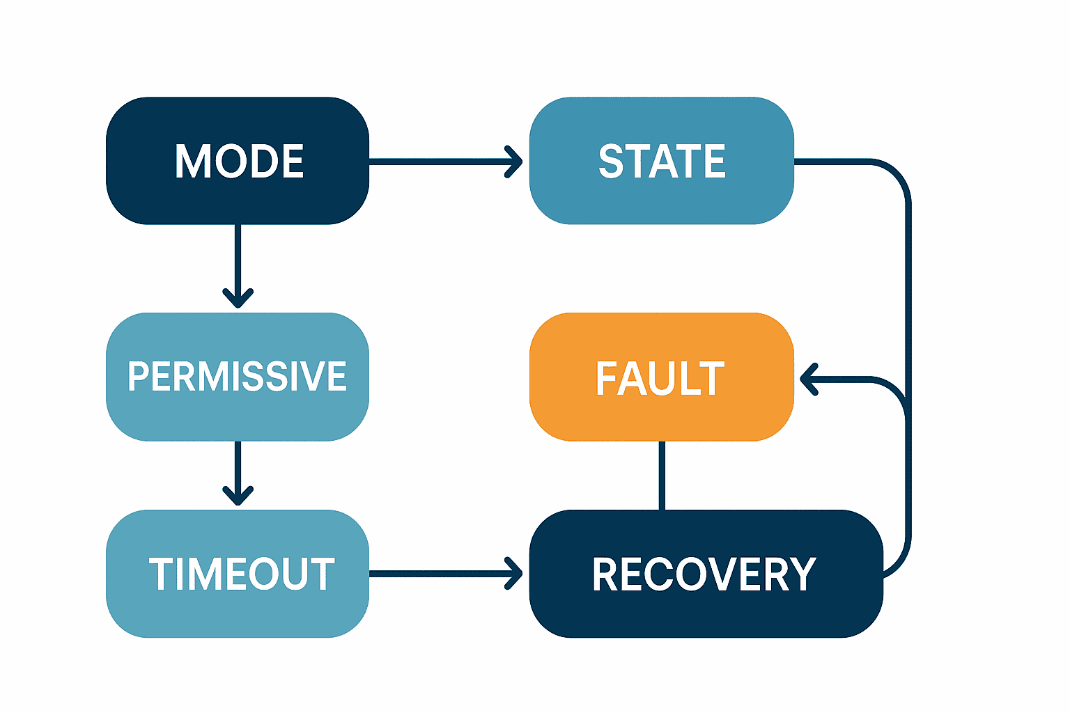
AUTO and MANUAL are modes. STOPPED, STARTING, RUNNING, HELD and ABORTED are states. Encoding both concepts in one integer or a group of hidden flags creates ambiguous combinations. Manual mode can be idle or active; automatic mode can be ready, starting, running, holding or stopping. Two explicit axes let the team define which combinations are valid and which are prohibited.
What belongs in the mode table
For every mode, define who can select it, prerequisites, available commands, motion or output limitations and the state entered after selection.
| Mode | Purpose | Example prerequisite | Example authority | State after selection |
|---|---|---|---|---|
| AUTO | normal production | home, recipe and required conditions verified | operator | READY |
| MANUAL | individual actuator check | automatic cycle stopped, part condition checked | trained user | MANUAL IDLE |
| CHANGEOVER | tooling and product change | production cleared | setup role | CHANGEOVER |
| MAINTENANCE | inspection and diagnostics | applicable energy-control procedure | maintenance role | MAINTENANCE |
These are design examples, not safety requirements. Hazardous-energy isolation and safety functions must be determined through the machinery risk assessment, independently of normal mode logic.
Define each state by entry, residence and exit
A name alone is not testable. For each state document entry actions, outputs and monitoring while active, normal transitions, abnormal transitions and exit actions. ISA reported the publication of ISA-TR88.00.02-2022, which applies ISA-88 concepts to automated machine states and modes and provides state-model, procedural, implementation and tag-naming examples. It can help establish a shared vocabulary; it is not a reason to copy a model without adapting it to the machine.
| Current state | Entry | Monitor while active | Normal transition | Abnormal transition | Exit evidence |
|---|---|---|---|---|---|
| READY | validate recipe and home | start permissives | START and all permissives → STARTING | permissive lost → STOPPED | cycle ID assigned |
| STARTING | energize required functions in order | start feedback | all feedback → RUNNING | deadline missed → ABORTED | start result logged |
| RUNNING | execute process | process and quality conditions | complete → COMPLETING | major fault → ABORTING | process result fixed |
| HELD | preserve defined process condition | resume conditions | approved resume → UNHOLDING | hold impossible → ABORTING | hold duration logged |
| ABORTED | establish non-hazardous stopped condition | cause and residual condition | cause cleared and approved → CLEARING | recurrence → ABORTED | recovery evidence logged |
The labels are examples. The essential point is that the table, PLC implementation, HMI display and event record use the same meaning.
Distinguish permissives, process interlocks and faults
Plants often call all three “interlocks,” although they serve different purposes. A prerequisite that prevents start, a condition that blocks one output during operation and an event requiring operator response should not automatically have the same latch, message or recovery behavior.
Permissives
Permissives are prerequisites for accepting a command: home confirmed, material present, downstream available, approved recipe loaded or a machine handshake established. If one is absent, show the reason for “not ready” without necessarily creating a new fault-history entry every scan.
Normal-control interlocks
A process interlock preserves sequence integrity or equipment condition, such as preventing machining before clamping or transfer before an axis reaches its position. Specify whether operation resumes automatically when the condition returns or requires a new command.
Faults
A fault is an event that requires a response, product disposition or retained history. Record a code, active state, relevant inputs, affected cycle or part, first occurrence and recovery time. “Cylinder fault” is less useful than “forward command issued; forward limit did not become true before the monitoring deadline.” The latter reports an observation without falsely diagnosing the valve, air supply, wiring, sensor or mechanism.
Specify a timeout as a behavior, not a timer value
A timeout definition needs the monitoring start condition, expected response, deadline, completion rule, destination state, output action, product action and retry policy. A number alone is untestable if nobody agrees when timing starts.
Calculation example (assumption): suppose normal actuator response is 0.8 seconds, the observed upper variation is 0.3 seconds and 0.4 seconds is reserved for communication and scan margin. An initial monitoring value could be 0.8 + 0.3 + 0.4 = 1.5 seconds, then adjusted using FAT and on-machine SAT data. The 1.5-second value is an illustrative assumption, not a general recommendation.
Continuing to drive an output after timeout may worsen a jam. Dropping every output immediately may also drop a part or destroy the known quality state. The team must distinguish a risk-reduced machine condition from a process hold that preserves product, combining machinery design, process requirements and risk assessment.
Make fault codes and HMI text part of acceptance
Each fault-code record should contain:
- a unique code and localized message;
- modes and states in which it can occur;
- the condition actually observed by the PLC;
- the machine stop or hold behavior;
- the disposition of the affected part;
- checks expected from the operator or technician;
- reset conditions and required authority;
- whether an automatic retry exists and its limit;
- the FAT test ID that proves the behavior.
In a multilingual factory, the code should remain common even when the message is translated. A Thai HMI and an English maintenance record can then refer to the same event without relying on an approximate verbal translation.
Design fault recovery as more than “reset”
Avoid a design where a reset button clears a bit and immediately re-energizes the sequence. Divide recovery into cause removal, acknowledgement, state consistency checks, product disposition, selection of home or restart point, and restart approval.
Assign recovery authority
An operator may recover a simple material shortage, while a servo following error, corrupted quality data or activation of a protective device may need maintenance or quality approval. Couple HMI roles to an audit event recording who confirmed what and when.
Control work in process
A mechanically recoverable machine does not guarantee that the interrupted part remains conforming. Track completed operations, measurements, traceability ID, hold duration and rework permission. Transition the part to resume, controlled discharge, quarantine or scrap according to the quality procedure. The PLC can carry the status; it should not invent the final quality decision.
Treat power restoration as a separate case
After a power loss, volatile data, physical outputs, communication sessions, servo positions and external-machine states may differ. Classify data that is retained, initialized or reconciled and define a specific power-up state. A normal fault reset should not conceal that reconciliation.
Manage the recipe and software as one tested configuration
The same PLC code can behave differently with another recipe, HMI setting, robot program or vision parameter. FAT evidence should identify the complete tested configuration: PLC, HMI, robot, vision, recipe and relevant drawing revisions.
For every update record the reason, author, approver, affected states, faults and product types, and the required regression tests. Online commissioning edits must be returned to the controlled master so that a later service visit cannot overwrite production with an older backup. For migration-specific issues, see PLC replacement and retrofit in Thailand.
Build the PLC FAT from a state table and fault injection
A FAT should not be only a production demonstration. It should apply a controlled stimulus to each relevant requirement and prove the expected state, output, message, product status, log and recovery behavior.
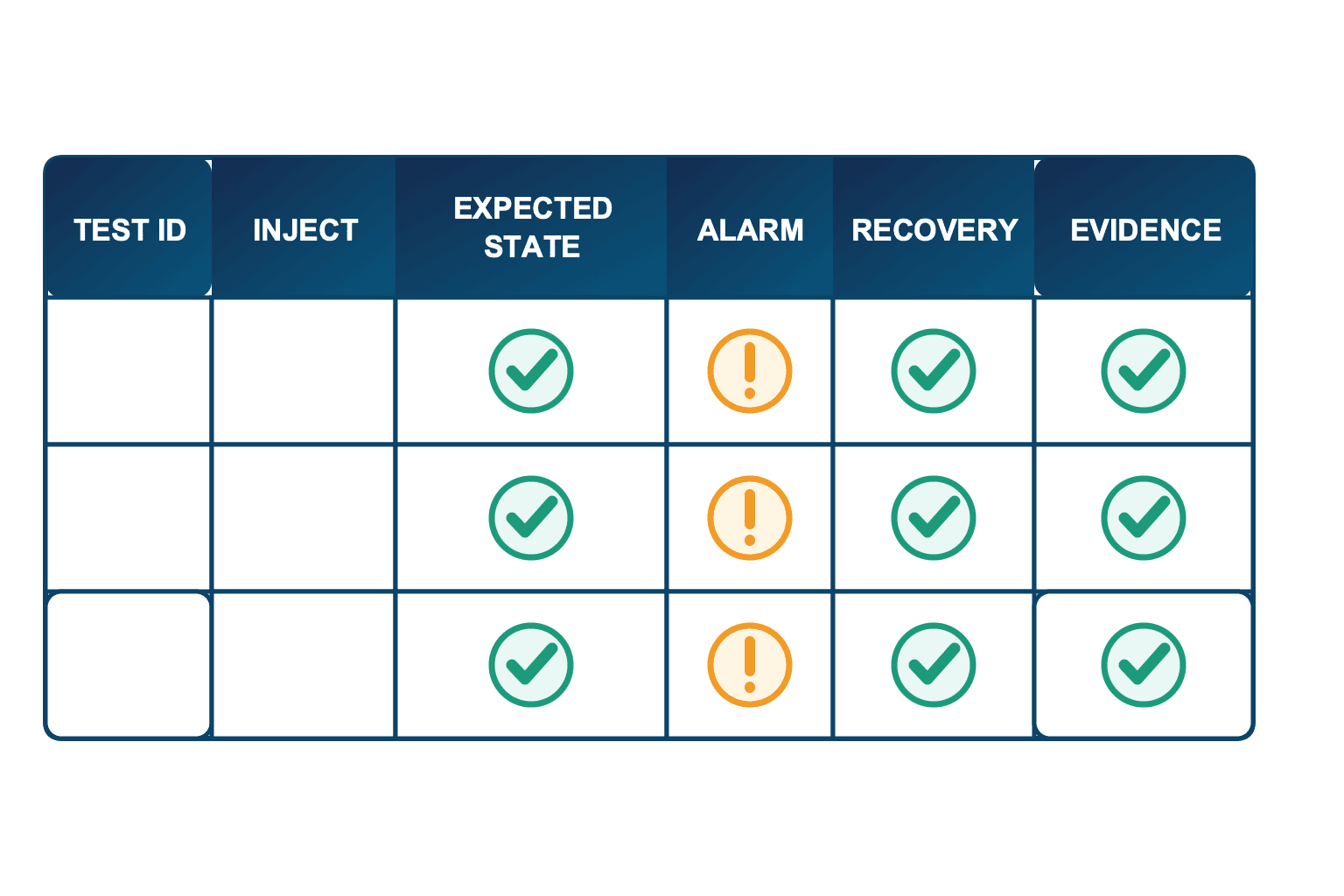
Columns for the fault-injection matrix
| Column | Purpose | Example evidence |
|---|---|---|
| TEST ID | link to a requirement | FAT-SEQ-xxx |
| Initial mode/state | reproducible starting point | AUTO / RUNNING |
| INJECT | missing input, communication break, invalid data | simulated input remains false |
| EXPECTED STATE | required transition | HOLDING → HELD |
| Output/product | machine and work-in-process response | transfer stopped, part on hold |
| ALARM | exact code and display | code matched |
| RECOVERY | removal, acknowledgement and authority | maintenance approval |
| EVIDENCE | event export, screen, trend, version | CSV and HMI capture |
Expand cases from each state: normal transition, absent permissive, expected input missing, input lost mid-step, stop request, mode-change request, communication interruption and power restart. Prioritize using risk, likelihood, difficulty of detection and product impact rather than attempting unlimited combinations.
Calculation example (assumption): eight states with three representative injected failures each produce 8 × 3 = 24 cases. Repeating all of them in three modes would produce 72 cases, but shared logic may allow justified representative coverage. These numbers illustrate scope estimation; they are not a prescribed test count.
Agree on the injection method
Forcing an input in software, using a simulator and physically disconnecting a device have different repeatability and risk. Before FAT, agree which signals may be simulated, which checks require the real machine, how forces are cleared and who may access a test mode. If a bypass remains in the production build, require authorization, prominent indication, logging and an automatic or procedural removal check.
Make pass/fail observable
“Stopped correctly” is not a pass criterion. Separate expected state, output, HMI code, product flag, event time and permitted recovery role. If the only evidence is the programmer’s online view, the buyer cannot later reconstruct acceptance. Define transferable evidence such as event exports, trends, screen captures and controlled video.
Divide FAT and SAT responsibilities
FAT can verify panel, PLC, HMI, simulator and assembled-machine behavior available at the supplier. SAT adds actual utilities, product, upstream/downstream machines, production network, users and host systems. A FAT pass is not proof of every production condition.
| Topic | FAT emphasis | SAT emphasis |
|---|---|---|
| State logic | all transitions, including simulation | representative transitions under real conditions |
| I/O | simulated or panel signals | real sensors and actuators |
| Timeouts | logic and fault destination | timing validity under load |
| Host interface | test service or simulated response | production MES/interface |
| Recipes | limits and invalid values | approved production product |
| Recovery | role, state and log behavior | site procedure and trained users |
Every SAT adjustment should be recorded as a difference from the FAT-approved configuration. Calling online changes “minor tuning” without capturing them makes the installed program, final backup and test result disagree. Broader equipment boundaries are discussed in custom special-purpose machine procurement in Thailand.
Connect the requirement to the audit log
A report is weak if it cannot identify which requirement and software configuration were tested. Link requirement ID, state model, software version, test ID, result, approval and production event vocabulary.
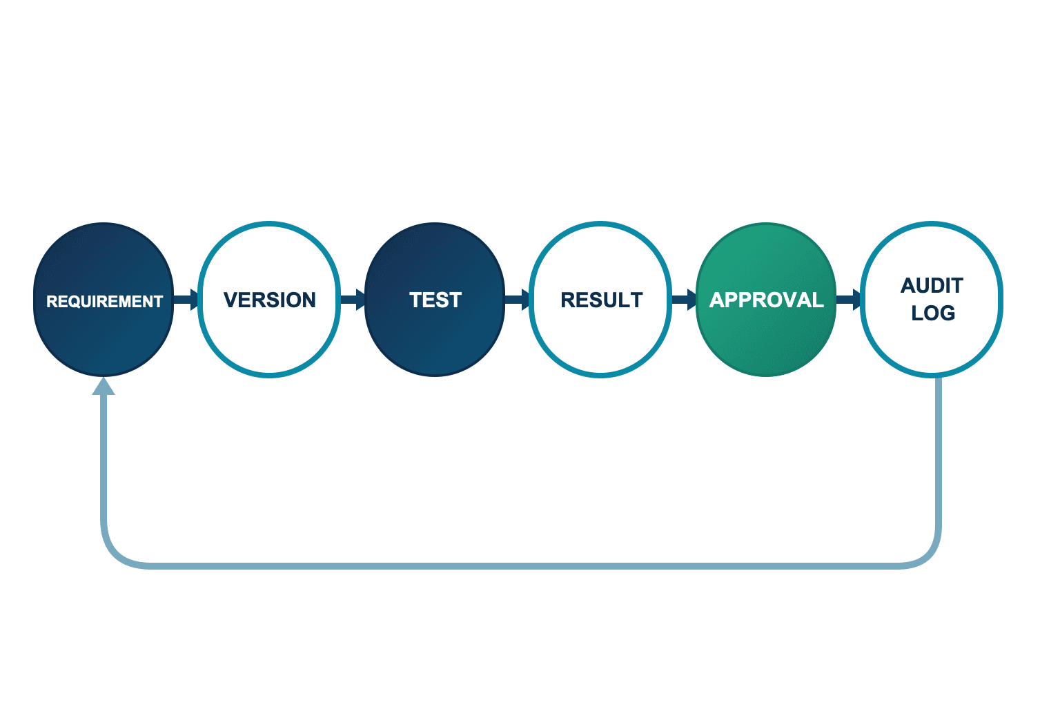
The evidence chain should answer:
- Which mode, state or transition implements the customer requirement?
- Which PLC/HMI/recipe configuration contains it?
- Which FAT or SAT test proved it?
- What measured result and attachment were retained?
- Who approved it, when and with what conditions?
- Can the same ID be traced in production fault and recovery logs?
This traceability supports focused regression testing when a fault message, transition or recipe limit changes. The audit log is not intended as employee surveillance; it reconstructs the event, configuration and authorized recovery decision. Retention and access should follow the customer’s quality and security policy.
Keep normal sequence control separate from functional safety
This boundary is critical. A stop condition, process interlock, emergency-stop display or recovery routine in a standard PLC does not by itself meet functional-safety requirements. ISO 12100:2010 provides principles and methodology for machinery risk assessment and risk reduction; ISO reports that edition as reviewed and confirmed in 2022. ISO 13849-1:2023 addresses the methodology for designing and integrating safety-related parts of control systems, including software.
Hazards, required risk reduction, safety functions, required performance, architecture, diagnostics and validation must therefore be handled separately by competent persons using the applicable standards and machine risk assessment. A normal-control state table can help manage the machine after a safety function operates, but it cannot replace a safety PLC, safety circuit or validated safety function.
The procurement specification should show responsibility boundaries among the standard PLC, safety PLC/circuit, drive safety functions, mechanical safeguards and operating procedures. If the standard PLC reads a safety status for display or history, do not describe that monitoring as the safety function itself.
BOI context for automation investment in Thailand
Thailand BOI’s first-half 2026 release reported 132 Smart and Sustainable Industry applications totaling THB 17.158 billion. Those values describe application activity; they do not guarantee approval or eligibility for any project.
BOI’s current measure states a minimum investment of THB 1 million, excluding land and working capital. It also describes a three-year corporate income tax exemption capped at 50% of qualifying investment, or 100% where at least 30% of machinery, automation or robot value is linked to or supports Thailand’s domestic automation machinery industry. Project scope, eligible costs, timing and the domestic-industry linkage must be confirmed with BOI or a qualified adviser. Do not build a business case on assumed approval.
A state specification, version manifest and FAT record can support a disciplined investment file, but they do not automatically satisfy BOI conditions. Keep technical acceptance and incentive eligibility as separate workstreams with an agreed evidence plan.
Procurement and acceptance checklist
Before quotation
- Define boundaries with product, host system and adjacent equipment.
- Attach a draft mode and state model.
- Include stop, hold, abort, fault and recovery, not only the normal cycle.
- Separate permissives, process interlocks and safety functions.
- Specify localized HMI messages, common codes and event export.
- Require controlled PLC/HMI/robot/recipe configuration records.
At design review
- Does every state have entry, active and exit behavior?
- Are normal, abnormal and prohibited transitions explicit?
- Does every timeout have a clear start point and failure reaction?
- Are reset and restart separate actions?
- Are power restart, communication failure and work in process covered?
- Is normal control clearly prevented from being presented as functional safety?
Before FAT
- Generate the fault-injection matrix from the approved state table.
- Make initial conditions, stimulus and expected result observable.
- Control test forces and bypass authorization.
- Freeze all software and recipe versions under test.
- Define correction, retest and conditional-acceptance workflow.
- Agree the evidence format and handover package.
At SAT and handover
- Validate timing under real load and record adjustments.
- Test host and adjacent-machine failures and recovery.
- Train each role on recovery and product disposition.
- Confirm the final backup matches the tested site version.
- Record open items, temporary controls, owner and due date.
- Establish a review process for production fault logs.
Common failures and how to correct them
Purchasing from a normal-cycle diagram alone
When the flowchart contains only normal production, abnormal behavior is left to the supplier’s standard or an individual engineer’s judgment. Add abnormal transitions and recovery conditions to the state table, then link each one to a FAT test ID.
Accepting the machine from a ladder-program review alone
Code review matters, but it does not replace observing what happens when an input or failure is injected. Base acceptance on test evidence that includes state, HMI message, output behavior, event record and product-quality flag.
Using one reset for every fault
A common reset erases faults with different causes, risks and authorization requirements, making recurrence and product impact difficult to trace. Define acknowledgement, cause removal, machine consistency and restart approval for each fault class.
Failing to return SAT site changes to the controlled release
If the delivered backup differs from the live site version, the next maintenance action can roll the machine backward. Record version, reason, impact and retest in the change record, then capture the approved final configuration again.
Frequently asked questions
What is sequence control?
It is control that advances machine conditions and outputs according to defined order and conditions. A testable specification includes modes, states, permissives, stops, timeouts, faults, recovery and evidence—not only the normal order.
Should I specify ladder logic or SFC?
Choose based on the controller, machine, supplier standard and maintenance capability. LD can make contact conditions easy to trace; SFC can make the step/state skeleton easier to review. More important is the traceability between the state table and code, clear naming, transition rules and testability.
What should a state-transition PLC FAT verify?
Verify normal and abnormal transitions, permissives, timeouts, output behavior, HMI codes, product status, event records and recovery authority. Fix the starting condition and injection method, then express acceptance in observable terms.
How should a fault-recovery sequence start?
Separate reset from restart. Confirm cause removal, machine consistency, work-in-process disposition, restart point and approval authority. Treat restoration after loss of power or communications as dedicated scenarios.
Can a PLC FAT prove machinery functional safety?
No. It can verify specified normal-control behavior but does not replace machinery risk assessment or the design, integration and validation of safety-related control functions under applicable standards.
Is a Thailand BOI automation incentive guaranteed?
No. The current measure has project, investment and cost conditions, and the applicable route depends on the specific facts. Confirm eligibility, calculation and application timing directly with BOI or a qualified adviser.
Conclusion
The acceptance boundary for sequence control should be modes, states, transition guards, permissives, timeouts, fault codes, recovery authority, recipe/software versions and audit evidence—not simply a functioning normal-cycle ladder. Derive a fault-injection matrix from the state table and use FAT and SAT to prove state, output, product treatment, message, log and recovery. Keep functional safety separate, and preserve the evidence chain from requirement through version, test and approval so the machine remains supportable after launch.
If you are planning a new or modified machine in Thailand and the state table or PLC FAT fault cases are not yet settled, you can still discuss the specification boundary with us. Use the TOMAS TECH contact page to review gaps between the purchasing document, supplier design and actual recovery workflow.
References
- IEC 61131-3:2025: https://webstore.iec.ch/en/publication/68533
- PLCopen Software Construction Guidelines: https://plcopen.org/software-construction-guidelines
- ISA Standards News Archives: https://www.isa.org/standards-and-publications/isa-standards/news/standards-news-archives
- ISA TR88.00.02 preview (2015 background only): https://www.isa.org/getmedia/300dbd50-d549-41ac-b372-a5e52f32fc97/tr_880002_preview.pdf
- ISO 13849-1:2023: https://www.iso.org/standard/73481.html
- ISO 12100:2010: https://www.iso.org/cms/%20render/live/en/sites/isoorg/contents/data/standard/05/15/51528.html?browse=tc
- Thailand BOI 1H2026 release: https://www.boi.go.th/index.php?_module=news&from_page=press_releases2&language=en&page=press_releases_detail&topic_id=139075
- Thailand BOI Smart and Sustainable Industry measure: https://www.boi.go.th/th/smart_sustainable


